|
 |
| Administration | |
|
|||||||||
|
Clickbank Promo Tools Dual Minato-Wheel Theory Written by: Jason Owens September 14th 2005 Here are my thoughts about the normal Minato wheel vs. the Dual Minato wheel.
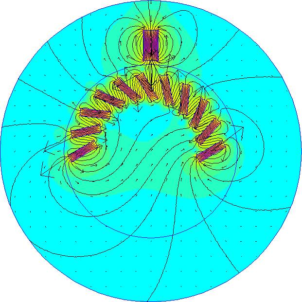
First, consider a typical flux diagram of a single minato wheel. In this example, I used 11 SmCo28 Bar magnets with the north poles oriented outward (just as in Jaros diagram). The dimensions of the magnets are 1/4 x 2 x 3/8 thick. The stator magnet is an NdFeB35 magnet with its north pole facing the wheel. The dimensions are 1 x 2 x 3.8 thick.
Here I want you to see the flux loop that I believe causes the sticky spot at the beginning of the track and the kick at the end of the track. You can see that the magnetic field of all the magnets is generally flowing in a counterclockwise direction because of the vector arrows. Other evidence of the loop is the region right under the magnets where the flux is dense stretching from one end of the track to the other (See Figure 1). Also note that the vector arrows coming out of the track magnets on the far left and right are much larger than the surrounding arrows. This shows that the field intensity is great in those regions because the track is generally behaving as one giant magnet. On the left we have the kick spot because of the large area of repulsion around the end, and on the right, we have the huge attraction sticky spot at the beginning of the track.
In my opinion, the key to correcting the problem is to isolate the magnetic field of each rotor magnet so that the giant flux loop will not occur. This should eliminate the sticky spots at the end (because the flux will not pool up at the ends in the first place), but the key is to do this without hindering the forces that make the wheel work. The simplest way to accomplish this would be with shielding around each magnet but placing shielding around each magnet will reduce the overall power as well.
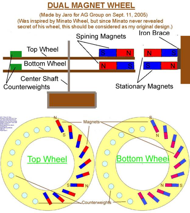
Jaros method is another good way of accomplishing the same effect without using shielding. The idea he is after is to simply redirect the magnetic flux from each magnet from flowing from left to right to flowing from top to bottom. This will create mini closed loops between the top and bottom magnets that will isolate each magnet pare (top and bottom) from its neighboring pare.
I ran some tests in Maxwell3D to verify this idea and from what I can tell; it does appear to be happening when the magnets are placed close enough to each other vertically. However, before I continue on to my results. I should point one thing out in Jaros diagram:
Placing a north pole stator against the left wheel will make it rotate clockwise and placing a south pole stator on the right wheel will also make it rotate clockwise. This is an important point to understand because the mechanism that could make this work has nothing to do directly with the fact that the poles on the stator and rotor magnets are reversed on each disk. The key here is the flux loop I explained earlier.
With the wrong distance between the top and bottom row of magnets, the wheels would just behave as one large wheel with two extremely strong kick and sticky spot. However, when the top and bottom disk are brought close to each other, the magnetic flux loop will begin to take effect and change the flow of the magnetic flux field. IF this does indeed occur, I hypothesize that the sticky and kick spots will be diminished or eliminated all together leaving just the force of the magnets on the tracks to propel the disks. Again, I feel the key here is the flux loop.
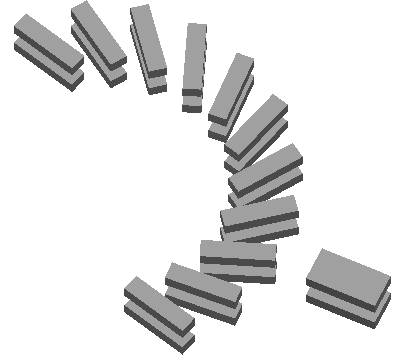
Here is a picture from my simulation in Maxwell 3D of the dual magnet Wheel:
This is a 3D flux diagram showing the magnetic fields of the magnets projected onto the sides of a cylinder. This appears to support my idea about the flux loops again. However, after running some Transient tests (simulating the motor in motion), I got very promising results.
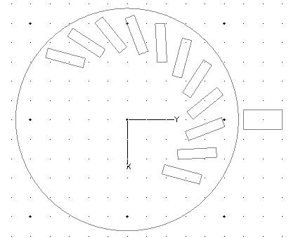
I ran two Transient tests. The first one was conducted on a simple one-disk minato wheel with a single stator magnet. I ran the test from 0 to 5 seconds with the wheel in the following starting position:
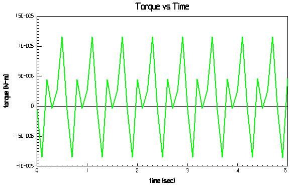
When the test was complete the results showed that the wheel didnt even move at all. So I changed the test and set the wheel to a constant velocity 100 RPM so I could see how the torque on the disk changed. Here are the results I got:
From the chart, one may observe that the positive and negative spike represent the kick and sticky spots as the wheel is rotated. The simulation may have run a little cleaner if I used a bigger stator magnet. Looking at the torque graph for the one-disk simulation, there are little sticky spots along the track showing that the stator is so small that it is being influenced by each individual magnet instead of smoothly transiting the entire track.
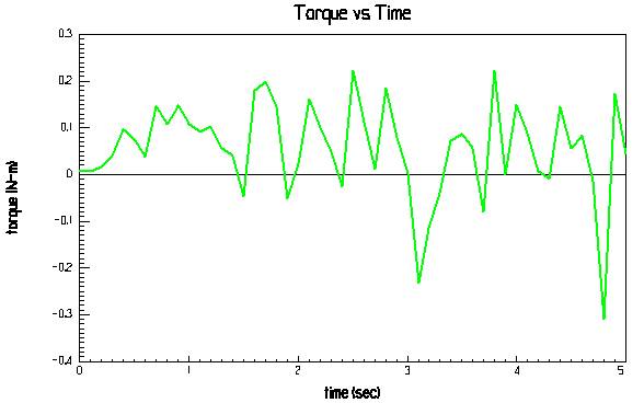
For the second test with the Dual Disk setup, things turned out quite differently. I used the exact same setup with the dual disk, only I didnt need to set the velocity to a constant value. When I put the disk in the same starting orientation, it self started and kept accelerating! The torque curve also looks different too:
Now, one can
clearly see that the majority of the torque is on the positive side of the
graph; however, since the velocity was not constant for this test, I needed to
set it to 100 RPM as in the last test so I could compare the results. Here is
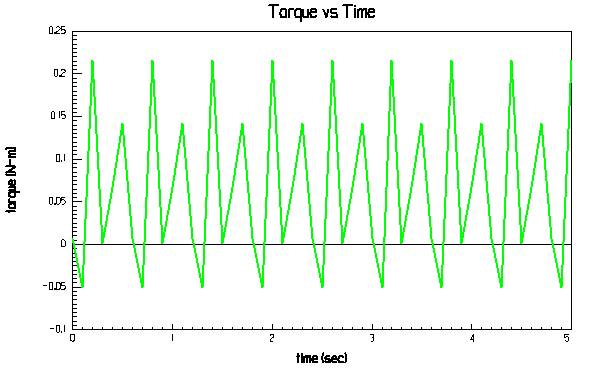
the constant-speed torque graph:
Something is definitely going on here! The torque curve is completely shifted upward giving the wheel a net force for rotation! Now, this is just a simulation, but it certainly gives strong evidence in support of this working. Definitely worth the effort to build. The beauty of all this is that there is no shielding required!
So in conclusion, test results strongly suggest that the model will run. The critical factor will be the gap between the upper and lower disk. My recommendation is to make the gap no longer then one magnet thickness apart. On the other hand, the gap should not be too close either or the flux will completely loop and there will be no force at all to drive the wheel. Finding the Sweet spot will be the key here in my opinion. If the design runs as stated, it also may be possible to put magnets all the way around the wheel since the flux loop is localized between each individual upper and lower magnet pare.
God Bless, Jason Owens |
|
||||||||||||||||||||||||||||||||||