by Alfred Evert
Link to original website: www.evert/de
|
Objectives Bessler probably build his wheel with much simpler constructional elements.
So now further versions of technical realisation are to research. I don´t want
to present here all ´mental wrong tracks´, however I will offer some rather
complicated theoretic ´detours´ for reflecting problems.
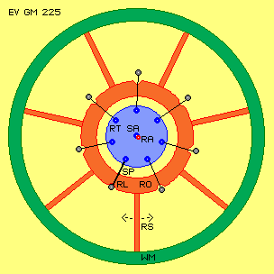
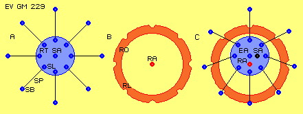
Arm, Spokes, Rotor At A as starting point is shown rotor-arm (RT, blue), fix installed at shaft
and turning around that system axis (SA). Outside at this rotor-arm (RT) spokes
(SP, grey, here e.g. eight) are installed, turnably beard within spoke-bearing
(SL, German Speichenlager) of rotor-arm. Outside at each spoke are installed
bolts (SB), at which rotor weights.
At inner border of rotor are eight triangle openings, which are called
rotor-bearing (RL, German Rotorlager). Into these openings previous bolts (SB)
of spokes (SP) are located. Openings are installed around rotor axis (RA) by
that radius, rotor at position shown hangs only at bolt of downside spoke. Bolts
of other spokes are located anywhere within their opening without bearing
weight.
At this picture at B is drawn longitudinal view through system axis showing
these elements. Rotor-arm (RT) here is drawn as disc, turning around system axis
(SA). Outside at disc spokes (SP) are beard turnably by spoke-bearings (SL). One
spoke here is represented by two rods symmetric to rotor-arm (RT). At outer ends
of spokes previous bolts (SB) are installed. At most downside bolt now rotor
(RO) hangs within its rotor-bearing (RL), while upper bolt is located at middle
of opening of its rotor-bearing. Outside of rotor, effective mass (WM) is
mounted.
At this picture at C an alternative with opposite arrangement is sketched.
Rotor-arm (RT) here is build by two discs, between which simple spoke (SP) is
beard turnable. Again at most downside bolt (SB) of spoke now hangs rotor (RO),
which in principle is build by two discs. So spoke has space to move within
rotor, however bolt comes into direct contact with rotor-bearing (RL) as soon
this spoke is weighted.
At E this variation of rotor is sketched by cross-sectional view. Rotor is
build by outer ring of effective mass and inner ring with its rotor-bearings
(RL), both rings connected via rotor-spokes (RS). Again it´s marked, rotor hangs
only by its downside rotor-bearing (RL) at bolt (SB), while all other bolts are
positioned far outside and contribute no support.
This constructional principle allows rotor as an ´eight-teeth´ element to
move within certain room and same time turning together with ´eight-teeth´
element rotor-arm around system shaft. Bearing of that function can be build by
diverse techniques. These possibilities of movements in principle now are basis
for following versions.
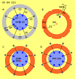
At A for example spoke-bearings (SL) are installed at rotor-arm (RT)
concentric to system axis (SA) by radius of e.g. 10 cm. Spokes are 12 to 15 cm
long, so spoke-bolts (SB) show distance to system axis of minimum 22 and maximum
25 cm (grey ring marks this room for movements).
At B only inner ring of rotor (RO) is drawn with its rotor-bearings (RL),
thus without its effective mass far outside. Rotor-bearings (RL) are arranged
concentric to rotor axis (RA) at radius of 22 cm. Upside right is sketched,
spokes (SP) must have sufficient room to move within rotor. Spoke bolts (SB)
however must be guided that kind, bolt arrives at its rotor-bearing (RL) as soon
as this spoke has to take weight, i.e. rotor temporary hangs at this spoke.
At C situation is shown where rotor hangs at both long spokes. Rotor axis
(RA) is positioned below system axis (SA), rotor thus is at its lowest position.
At D, rotor got lifted into its uppermost position. Rotor hangs at both shortest
spokes. At this example, rotor axis is located at level of system axis.
So only spokes most downward are bearing weight of rotor. Other spoke bolts
reach far outside of their rotor-bearings (and finally land there when taking
weight). This picture also shows, spokes are not in radial direction to system
axis all times, but swivel around spoke-bearing (and within area of rotor) while
revolution of system.
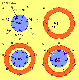
Picture EV GM 222 shows situation analogue to previous picture, however now
are drawn only seven spokes. Each pair of spokes show lengths of 15 and 14 and
13 cm, however only one spoke is 12 cm short.
At lowest position (here sketched at D) rotor hangs at most long spokes. At
uppermost position (here sketched at C) rotor hangs only at that one shortest
spoke and thus in most labile position, i.e. rotor easy can tip over, here e.g.
left side down.
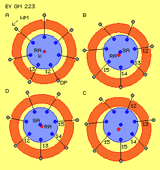
Fall and Brake In addition to normal turning speed around system axis, now rotor turns
around fulcrum (DP), which is represented by bolt of spoke 12. Rotor axis
swivels around that turning point left-downward (see dotted arrow at RA).
Rotor can fall relative far because next supporting point is bolt of next
spoke 13, which is longer than current spoke 12. Decisive however is, effective
mass at its much longer radius can fall much longer distance, so far left side
kinetic energy increases (here only marked by dotted arrow at WM).
That relative falling goes on (like sketched at B) via each longer spoke 13
and 14 until long spoke 15 (as sketched at C). Rotor now is running far ahead of
rotor-arm (as far as possible within room to move).
This running-ahead is reduced when rotor comes to shorter spokes. This
turning-lead might end when rotor weights e.g. at spoke 13 (like sketched at D)
and next will hit onto short spoke 12 again, thus is lifted to uppermost
position.
At this phase, previous falling becomes delayed - however movement of
effective masses are not braked down correspondingly. Opposite, turning of rotor
is intensified, as shown upside and at previous chapter in details. This delay
and swinging of effective mass downside right of supporting point affects
additional pressure at this spoke. Accelerated turning of rotor masses ´pulls´
spoke ahead in turning sense, resulting usable turning momentum - even rotor
axis should be positioned right side of system axis (like marked at D).
Usable turning Momentum At C is sketched how falling-downward goes on, as supporting point (AP) now
is represented by next longer spoke. This spoke at first stops tilting movement
(by force in direction of dotted arrow). This supporting force however can not
affect direct at effective masses, but especially mass left side now turns
faster around new supporting point.
At D now delay of falling is sketched, as next supporting point (AP) is
following short spoke. Also here, supporting force affects into direction of
rotor axis. In relation to effective masses however, that force can effect only
by right angles at connecting line between both masses. This component of force
is drawn here and its supporting point is marked by KK, left side of rotor axis.
By pure static view, now gravity forces of right mass would work at longer lever
arm.
Combination of gravity and kinetic energy of both masses however results
quite different relations of forces, which here are marked once more. At right
lever-arm of that ´seesaw´ weights only small downward directed force (because
inertia force TK reduces gravity force GK of that mass). At left lever arm
however affect both forces by likely vectors versus that blocking of its
movement at point KK.
As described upside, left mass thus swings around new supporting point and
right mass is slinged upward towards left correspondingly. At support-basis of
that ´seesaw´ weight total counter-forces of all movement deviations (see
double-arrow). This pressure affects downward right side und results turning
momentum (DM, German Drehmoment) of system.
Like already at EV GM 220 at E, rotor here exists of inner ring with
rotor-bearings (RL) and outer ring of effective mass. Both rings are connected
by some rotor-spokes (RS).
Solutions of previous chapter were ´round stuff´, as at Rhönrad round wheel
did roll alongside round eccentric wall resp. gear-wheel did roll within
gear-rim. Now here this solution works with spokes between rotor-arm and rotor
and movement process is ´bumpy stuff´ as weight tumbles from one bolt to next
bolt. So some damper should be installed at spokes. In addition would be
advantageous, if these spokes (RS) between rotor rings would be elastic, so
relative swinging ahead and back would be possible (like marked by dotted
arrows).
Increased Turning Momentum At B are shown consequences, if momentary now system shaft has to take higher
load. Rotor goes on turning, while rotor-arm (RT) turns less. Previous straight
line of forces between system axis and rotor supporting point now becomes
bended. Rotor will pull rotor-arm ahead. Rotor axis is shifted to left side.
Increased turning momentum comes up, corresponding to increased load at system
shaft.
At this process, also following spoke builds an angle to radial direction. At
next phase, this spoke has to take weight, like marked at C by thick lines. Now
weight does not hit onto this new supporting point in radial direction to system
axis, but forces affect stretching of that bended line (from SA via SL to RL).
Rotor-arm (RT) thus is pulled ahead by most strong lever-arm effect.
Deceleration of falling movement of effective mass thus becomes more ´soft´
and also tilting movement of rotor axis is no longer blocked abruptly. As a
result, this angled-line exists longer time (like sketched at D), until lastly
stretched position comes up analogue to situation at A.
So strange enough, this system generates increased turning momentum if taking
increased load, for certain time. If at following phase load is reduced, system
falls back to starting situation. System-shaft and rotor-arm turn slower at
high-load-phase and catch up delay at following low-load-phase.
Two different Legs At A is drawn ring-shaped rotor-arm at centre, which (opposite to previous
rotor-arms) is not firmly fixed at system shaft, but can turn free around system
axis. This element thus is called ´free-arm´ (FT, German Freier Träger, green).
Bearings of free spokes e.g. could be installed at radius of 4 cm around
system axis, free spokes could be 19 cm long, rotor with its rotor-bearing thus
could hang maximum of 23 cm downside of system axis. Each free spoke (FS) is a
short spoke.
At B ´normal´ rotor-arm (RT) is drawn analogue to previous conceptions, i.e.
this rotor-arm is firmly fixed at system shaft. However only four ´normal´
spokes (SP) are turnably installed at this rotor-arm (RT). Spoke-bearings (SB)
are arranged concentric around system axis e.g. at radius of 10 cm, spokes are
14 cm long, so rotor with its rotor-bearing can hang maximum 24 cm downside of
system axis. Each normal spoke (SP) is a long spoke.
At C these elements are combined. Momentary rotor weights at downside normal
spoke (SP), i.e. rotor is at its lowest position. Shifted to normal spokes, free
spokes (FS) interact with next rotor-bearing (RL). Thus rotor is lifted and
allowed to fall down from spoke to spoke.
At further turning (at D) rotor weights at normal spoke (SP) and following
free spoke (FS). Rotor practically stands at long and short leg same time. By
this position, rotor-arms and rotor can go on turning. Normal spoke pulls rotor
to right side, however does not lift rotor. As free-arm (FT) can turn free
around system axis, free spoke (FS) at first will escape that load, lastly
however centre of rotor-weight will come to position direct upside of supporting
point of free spoke (FS).
This situation is shown at E, where rotor now is at high level. Depending on
lengths of spokes, there can come up angle between radial direction (R) and
spoke (SP). At F is shown, how next moment rotor tilts down to left side onto
next spoke (SP). This falling motion is decelerated at the following with
effects mentioned upside.
Like mentioned upside, Bessler possibly tested this variation - or at least
it´s worth to be tested. When searching for simple solutions, this mechanism
however seems to be rather complicated. Simple prerequisites for usage of
gravity demand corresponding clear and simple mechanics.
Clear Solution At A ´normal´ rotor-arm (RT) is shown, thus firmly fixed at system shaft and
(at first) turning around system axis (SA). At its outer border again
spoke-bearings (SL) are installed, within which spokes (SP) are beard turnably.
At outer end of spokes again spoke-bolts (SB) are installed and at one (or two)
downside spokes rotor weights. All spokes now show same lengths (opposite to
previous solutions).
At B again is shown inner ring of rotor (RO) with its rotor-bearings (RL) for
taking previous spoke bolts. Like mentioned upside, rotor must be build that
kind, each spoke has room to move within rotor, however when a spoke takes
weight, its bolt must land within rotor-bearing (RL).
As second basic prerequisite for usage of gravity was defined, rotor-axis
must be accelerated versus direction of gravity. This is done at the one hand,
if rotor axis is lifted and at the other hand, if downward motion is delayed. At
previous solutions, these both aspects were mixed as spokes of different lengths
were used.
Opposite to all previous conceptions now here at C is drawn essential changed
arrangement: rotor-arm (RT) may not turn concentric around system shaft, but
rotor-arm must be installed eccentric to system axis (SA, thus to system shaft)
around an eccentric axis (EA).
Rotor-arm (RT) well could be round disc, firmly fixed at system shaft out of
its centre. This disc could also be mounted concentric to system shaft, however
decisive is that spoke-bearings (SL) are arranged at a circle around eccentric
axis (EA).
Finally by this arrangement, each prerequisite is represented by each
separated constructional element: Other end of spoke is beard movably within rotor-bearing (RL) of rotor (RO).
Here spokes simply and schematic are drawn only as connecting lines between
outer border of rotor-arm and inner border of rotor. Bearings and construction
of spoke can be realized by different techniques. These connecting lines e.g.
could be rods becoming shorter and longer like telescopes, however its maximum
length is determined (e.g. when taking weight at downward position). As simple
version, rotor bearing (RL) e.g. could be a slot within which spoke bolt (SB)
can move linear.
Rotor here is drawn as disc, however could also exist of inner ring with
rotor-bearings and outer ring with effective masses (WM), both rings connected
by some rotor-spokes, like upside already mentioned at one version.
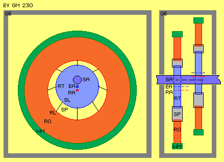
At longitudinal view this rotor-arm (RT) with its eccentric axis (EA) is
positioned downside of system axis (SA), in most downside spoke (SP) rotor (RO)
hangs in its lowest position. Right side at longitudinal view second assembly is
arranged at system axis. Rotor-arm with its eccentric axis there is positioned
upside of system axis. So this second module is shifted by 180 degrees to first
module. The more modules are installed at system shaft, the more steady system
will run and the more steady this gravity motor will show turning momentum.
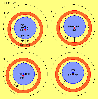
Clear Process Some distances are marked, e.g. distance between three axis each are 2 units
long, radius of rotor-arm (RT) 15 and inner radius of rotor 20, so spokes show
(net-) lengths of minimum 3 and maximum 7.
At B system shaft did turn 90 degrees, i.e. eccenter axis now shows to right
side, i.e. rotor is lifted at this phase. After further turning at C, eccentric
axis is upside of system axis, i.e. rotor arrived at its uppermost position. Now
rotor can fall down (at D) and downward movement of rotor axis gets decelerated
(back to starting position at A).
Rotor here always is drawn hanging in its downmost spoke. However one can see
well, rotor at every phase has room to move and thus can take positions
corresponding to each affecting force. Indeed, rotor will run ahead turning of
rotor-arm (and thus of system shaft) at some phases.
When rotor axis is lifted (previous situation B) rotor axis tilts below
system axis. At phase of falling (previous situation D) rotor will swing far out
towards left side. At phase of delay (back to previous situation A), left side
of rotor will swing vehement downward-right. At this phase, effective masses
´pull´ at spokes in turning sense of system, and automatic will come up angle
(analogue previous picture EV GM 227) between radius (SA - EA) and spoke
(previous SL - RL).
So now it becomes clear, why upside was searched for ´eight-teeth gear-wheel´
running within ´eight-teeth gear-rim´. This conception now corresponds to
solution of Rhönrad, however now here transmission of forces is done much more
effective by spokes used. This conception corresponds also to gear-wheel and
gear-rim, however here forces are transmitted not only by each one tooth (thus
lastly radial) but by spokes in variable positions.
It´s well to recognize, spokes take differing angles and show differing
lengths. However these motions are much more harmonic than at previous
solutions. Like mentioned upside, spokes are to construct by diverse techniques.
For example, its length are variable if using telescope-rods or sledges within
rotor-arm or within rotor could be used (or other techniques like discussed at
following chapters). At any case however, spokes must be beard turnable at both
ends - like this animation shows.
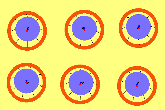
Here is only shown - already relative smooth - swinging of inner rotor ring.
Effective masses at much longer lever arm (and even at rotor-spokes some
elastic) will move more steady. Even acceleration and deceleration of masses are
relative small, forced changes of tracks however will produce enormous inertia
forces - and usable turning momentum.
Past and Future At the other hand and rather sure, Bessler had tested just these versions,
like discussed at next chapter Mysteries. After this excursion into
past, following chapters will come back to actual and future questions.
Evert / 04.04.2006
|
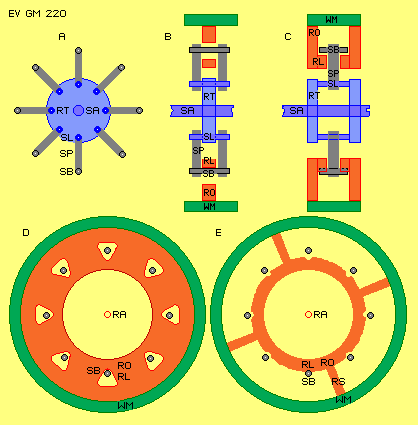 At D, left side below at this picture, rotor (RO, red)
schematic is drawn, at which outside effective mass (WM, German wirksame Masse,
green) is firmly fixed. Rotor again shows central opening, so rotor never comes
in contact with system shaft.
 Turning, Lifting, Lowering
 Labile Position
 This tipping-over adds to normal turning motion, so rotor
in total now turns faster. Rotor axis wanders within system ahead (in turning
sense). Already tilting around previous fulcrum (DP) affects turning momentum as
this spoke bolt is pressed to right side. At a whole, now rotor weights at
rotor-arm left side of system axis, so also by pure static view un-balance resp.
turning momentum exists.
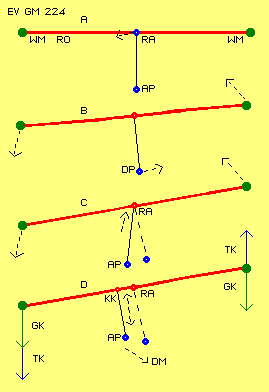 At B are marked ways of following movements. Supporting
point becomes fulcrum (DP), wandering in space towards right side. Rotor axis
swivels some towards left around this fulcrum, at much longer distances however
effective masses (see dotted arrows), left side down and right side up.
 Swinging ahead and back
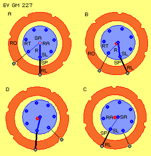 At picture EV GM 227 previous gear is shown again. At A
rotor (RO) hangs by its downside rotor-bearing (RL) at downside spoke (SP),
which is marked by thick line. Via spoke-bearing (SL) thus rotor weights at
vertical radius (R, thick blue line) at system axis (SA).
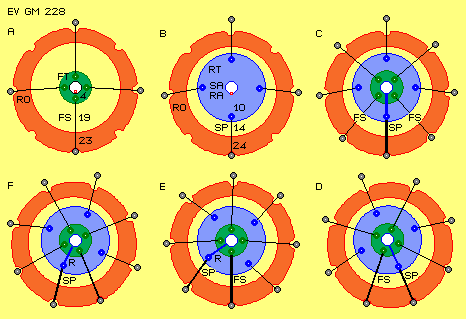 At this ring turnable are installed four ´free spokes´
(FS), which like previous spokes interact via bolts with rotor-bearings of
rotor. At position drawn, rotor hangs within downside free spoke.
 At C both elements are combined and here rotor weights at
downside spoke. As now all spokes are likely long, rotor is relative free to
move (e.g. no longer limited by short spokes). Depending on affecting forces,
rotor e.g. could also swing really far left side.
 Clear Design
 At
picture EV GM 231 central ´gear´ (without effective mass of rotor) is shown in
four situations. At A is shown previous starting situation. Rotor-arm (RT) resp.
its eccentric axis (EA) is positioned below system axis (SA). Rotor (RO) weights
at downmost spoke (SP). Dotted circle is concentric to system axis, so momentary
position of elements is to locate easier.
 Smooth Swinging