by Alfred Evert
Link to original website: www.evert/de
|
Objectives At diverse proposals for solution of previous chapters was found, mass is not
to guide at circle-round track but has to move at uneven tracks, in order to
break that general symmetry of all processes and power effects. At this picture
at B for example is shown a track, at which effective mass can fall nearby free
within a sector (D), later on is turning relative steady at circled bow (E) by
constant radius, which at following upward-phase is reduced, so mass comes back
to track more inside (F).
Objectives of these conceptions in principle was to transfer kinetic energy
of free falling motion into turning momentum. Contrary to these attempts of
solutions now stands general knowledge, lifting and lowering of masses is
force-neutral at any case, no matter by which process or leverarm-system that
job is done. So by that point of view, naturally all these systems are symmetric
concerning demanded and ´produced´ energies.
Nevertheless, despite of balance in general, also valid in general is fact
schematic shown at this picture at C: masses of rotor systems with horizontal
axis don´t weight at all phases same kind onto spokes. At downside positions
inertia- and gravity-forces add to stronger forces, marked at this picture as
phase G with strong pulling forces. At following upward-phase (H) for example,
radial forces are much weaker. Previous surplus of forces thus should be usable
for pulling inward masses at that phase.
Prerequisite thereto is, forces are to store intermediately, e.g. in shape of
spring´s tension. Also based on that idea I already made several proposals at
different chapters. However, affecting forces are to use as effective turning
momentum only if forces don´t work radial but into tangential direction.
Objectives of this chapter here thus are to design corresponding
leverarm-system.
Leverarm-System At rotorarm is installed rotor bearing (RL, German Rotorlager), around which
rotor (RO) can swivel. Rotor here for example is drawn like circle-bow, which
maximum can be half circle long. So at one axial level are to arrange two of
these rotors.
There is an other connection between rotor and rotorarm, which here is called
pulling-rod (ZS, German Zugstange). This rod at the one end is beard swivelling
within rotor and this bearing here is called pulling-joint (ZL, German
Zuglager). At the other end, that rod is guided by swivelling bearing of
rotorarm, here this bearing is called spring-joint (FL, German Federlager).
As rotor can swivel, distance between both bearings is variable. Pulling-rod
(ZS) can glide within spring-joint (FL) and phasewise rod will reach far out of
spring-joint (here at upside rotor). There is also installed a spring-element
(FE, German Federelement), which is compressed at stretched position. This
drawing is only schematic. Function of both bearings e.g. could also be
vice-versa, i.e. rod phasewise could reach outside of pulling-joint (ZL) and
spring-element (FE) could be installed outside of. For example, pulling-rod (ZS)
could also be constructed as telescope-rod with springs integrated.
Rotor downside at C is at that phase marked G at previous picture: effective
mass of rotor wants to move downward by gravity like inertia, i.e. mass is
weighting at spring, so spring is tensioned (while rotor upside weights at its
supporting point and its spring is slacken in total).
At this picture at D rotor did turn by 90 degrees and phase of start of
spring-tension (left) is shown and also phase of expanded spring (right). Rotor
left side at D swings outward, so spring-element (FE) lastly gets compressed
(like described at C at downward rotor). Rotor right side at D shows weaker
forces into radial direction (compared with it´s previous position), so spring
there is able to draw mass inward. That phase thus corresponds to sector H of
previous picture (however at this position spring is slacken already in total).
If for example right-side-down frontside-mass already is guided upward,
backside-mass still moves downward. At the following, frontside-mass by
swivel-inward ´gets out of way´ for following mass. As soon rotor leans at
supporting point (here marked by dark-blue circle), mass weights only at system
axis. Mass there ´glides´ downward sloped surface, pulling rotor-joint over its
uppermost position towards left side. Frontside-mass there already swings
outward while backside-mass even is lifted towards left-side-up. Afterwards,
rotor takes position like circle-bow nearby concentric to system axis.
So masses as a whole, here move at asymmetric track like already shown upside
at picture EV FKM 01 and which shape of track was intended rather advantageous
at earlier chapters. At that conception here however, track of free falling and
lifting of masses are not decisive. Effect of this machine here is based only at
work of spring-element.
Tension of Spring At each mass-part are drawn constant gravity-weights (G1 and G2) as vertical
black lines. Inertia-forces (T1 and T2, German Trägheitskraft) of each mass are
marked by tangential black lines, here e.g. of half length of gravity-forces. By
addition of both effective forces are each resulting forces (R1 und R2). Both
masses in total affect pulling-force (RZ, German resultierende Zugkraft) by
vectorial addition of previous resulting forces. Rotor at each position wants to
move into each direction by each strength of forces.
By this construction - at static view - naturally comes up backward (towards
left) showing component at rotor-joint (which thus would be negative momentum at
RL). However it´s important, backside-mass (M1) shows stronger resulting force
(R1) than frontside-mass. Backside-mass is also positioned some left of
spring-element (FE). So backside-mass affects pulling down-ahead of rotor-joint
(RL), thus positive momentum.
At the other hand, spring is tensioned some earlier, e.g. already as
rotor-joint (RL) and spring-joint (FL) are positioned left side of system axis.
Mass in total there hangs downside of these two bearings. As soon as spring is
tensioned at its maximum, this leverarm-system works like fix installation of
masses at rotorarm (RT), i.e. rotor by that position moves through its downside
phase.
Extension of Spring Remaining vertical power-component (vertical dotted line) is to take by rotor
bearing (RL). This joint however has not arrived its downmost position. So even
within that phase of starting upward-motion, positive turning momentum affects
at this rotor-joint (RL) - however again only because backside mass shows
stronger forces.
At position shown at C now spring is slackened completely, however also there
is to see importance of these both mass-centres: upside mass already swings to
left side while downside mass still moves to right side. Both inertia forces are
overlaid by gravity forces resp. resulting forces R1 and R2 are reduced and show
in different directions. Both mass parts practically want to turn around
pulling-joint (ZL), while rotor-joint (RL) naturally has to lift rotor.
Forces and counteracting Forces Opposite to simple spoke present concept has only some more ´complicated
suspension´: while effective mass (preferably of long stretched shape) is at
downside position, joints of its leverarm-system still are left side of system
axis. Normal tension within material of solid spoke thus is transferred (at
least by parts) into tension of material of spring. This tension of spring is
´for nothing´ because done by gravity and inertia. At the other hand, motion´s
process, lifting and lowering and rotation of mass around system axis is
unchanged.
At the beginning of upward-phase now each resulting force becomes weaker (in
principle because gravity weights now vectorially are reduced more and more by
upward-showing intertia (resp. centrifugal) forces). Energy intermediately
stored within spring now is strong enough to pull mass inward (practically at
first ´lighter´ frontside mass, later on also backside mass).
At this phase of ex-tension of spring, pulling-rod (ZS) shows to right side
and spring-joint (FL) is positioned downside of system axis. Pressure forces of
spring affects at spring-joint (FL) - into tangential direction. So expanding
spring does that workload which results positive turning momentum. That force
demands counteracting force, which is represented by remaining power-component
of rotor masses which still shows right-side-outward. As spring at the one hand
is pulling masses inward, same time spring is pulling rotorarm (RT) ahead in
turning sense of system.
Once more is to point out importance of previous two mass centres: that
relative turning around pulling-joint (ZL) at previous picture EV FKM 05 at C,
by relative view exists already some earlier. Pulling force of spring does not
weight at rotor-joint (RL, with corresponding negative momentum), but spring is
pulling frontside mass (with its relative weak forces) around backside mass
(with its still much stronger forces showing outwards). Fulcrum of that motion
resp. power-affect thus is each backside mass part.
This process can work only if backside masses of rotor represent an
´inertia-centre´ within space. Extension of spring e.g. would be without effect,
if mass by itself would fall inwards. That´s case if wheel turns too fast, i.e.
spring is tensioned until rotor right-upside tilts inward by itself.
So after system is started turning, phasewise is build up tension of spring.
By work of spring at phase of ex-tension, positive turning momentum is achieved.
System will accelerate by itself up to certain maximum speed. Just below that
maximum revolution, surplus of accelerating forces are to draw off system as
usable turning momentum.
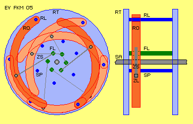
This principle of motion´s process is to realize by diverse techniques. So at
picture EV FKM 05 is shown previous rotor- and leverarm-system only by rough
sketch, by cross-sectional view and longitudinal view (and elements only drawn
by parts). Two of these rotor-rod-modules are to install at one axial level
(pointed out at this drawing). Between two rotorarm-disks could be installed
even six rotor-rod-modules.
As mentioned upside, pulling-rods (ZS) and its bearings and that spring could
be realized different kind, e.g. by telescope-rods. Area of swivel of rotor
could be much less than shown at previous pictures. However, effective mass of
rotor should not be concentrated (e.g. at pulling-joint ZL) but should be shaped
long stretched, so parts of masses run at different tracks with differing
resulting forces.
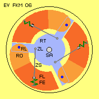
In order to show wide variation for realizing this principle, at picture EV
FKM 06 schematic is shown an other example. At system shaft (SA) is installed
rotorarm (RT) in shape of three rods. At each end of rods are installed each
rotor-joints (RL). Rotor (RO) is shaped as circle-segment of some 120 degrees.
So at this picture, rotor downside left shows phase of tensioning of spring
(spring is compressed). Rotor right side at this picture already got pushed
inward by spring (spring extended to its normal length). So spring must be
strong enough to do that work just before rotor comes into vertical position
upside of rotor-bearing (RL). Rotor upside at this picture is positioned inside
and rests at rotorarm (RT).
At this design, area of swivel of rotor is rather small. Large part of
available surface is represented by effective masses. Cross-section of rotor
e.g. could well be square. Three elements thus are to install at one axial
level, so also three work-strokes by three springs occur at one revolution of
system.
This example once more demonstrates, relation of leverarms and masses and
turning speeds and spring´s characteristic must be coordinated well. Spring must
be tensioned at its maximum left side down, where mass is shifted outward a
little bit. Rotor right side is pressed inward and rests inside until nearby
10-o´clock-position. So centre of all weights in total is positioned some left
of system axis all times. So that system could really start by itself resp. this
permanent unbalance of weights represents also some positive turning momentum.
Naturally this motor will show the more performance the stronger springs are,
i.e. the more heavy weights are installed, the larger radius of machine and the
stronger inertia forces are working at most large lever arms. However that
machine must not be large like ´Bessler-Wheel´ with diameter more than three
meters, because no free falling of masses is necessary. There is also no
transfer of energy by impulses, so that motor will work quite silent.
However this system must turn relative slow like Bessler´s wheels did
(probably less than 60 rpm), so springs have time enough for working process.
Optimum relation of all leverarm lengths, weights and spring´s characteristics
could be calculated theoretic, however will be found faster by practical
experiments.
Solution for using gravity by pure mechanical devises must be ´simple´. So I
hope some handcrafts are convinced by previous ideas of that simple design and
want to approve suggestion by real construction.
Evert / 10.12.2004
|
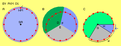 At picture EV FKM 01 at A schematic is shown effective
mass (WM, German wirksame Masse, red points) steady turning around system axis
(SA) at circle track (here left-turning is assumed all times). There can not
come up usable forces by this totally symmetric arrangement, e.g. centrifugal
forces affect only tension within material of spokes.
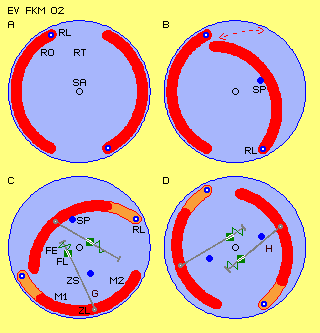 At A both rotors are at vertical positions. At B is shown,
rotor (right side) can swivel inward until leaning at a supporting point (SP).
At C this construction did turn by 90 degrees and there are drawn further
elements.
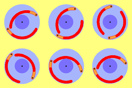 At this animation one can see motion´s process of
effective masses (dark-red parts of rotors). Naturally, masses in front of
rotors move at other track than masses further backside of rotors. At motion´s
processes like this, one may not think masses theoretical concentrated at one
central point, one must look at two centres of masses at least (like upside
already marked by M1 and M2).
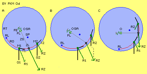 At A resulting pulling force (RZ) exactly shows into
direction of pulling-rod (ZS), i.e. spring-element (FE) there is tensioned at
its maximum. Whole rotor there hangs at spring-element, diagonal downside-ahead.
 Construction
 Second connection between rotor and rotorarm now here is
arranged that kind, pulling-joint (ZL) is installed at rotorarm (RT) and
spring-joint (FE) is installed at rotor. Spring-element (FE) is installed
outside (e.g. for easier adjustment). These elements are arranged that kind,
centre of weight of rotor hangs vertical down at pulling-rod (ZS) when rotor is
positioned left side down.
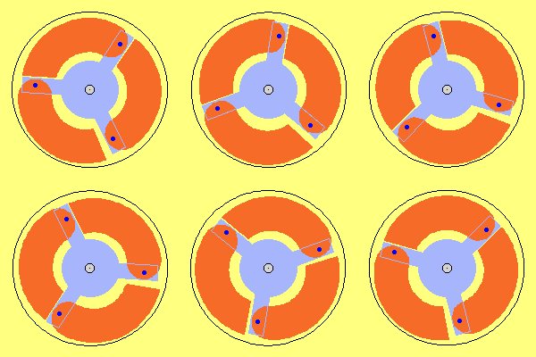 This animation shows motion´s process. Swivelling-outward
of rotor starts just after rotor-joint passed its uppermost position.
Motion-inward of rotor starts already before rotor-joint comes to its most
downside position. Relative small motions are to recognize at gaps between rotor
and rotorarm and also by surrounding black circle.