by Alfred Evert
Link to original website: www.evert/de
|
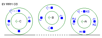
Objectives At previous ´Ringwheel´-chapter was noticed, system of ´flying wheel plus
hilly road´ easy could be copied by mechanical model. Objectives of this chapter
now are to precise this concept.
Rotation and Translation If wheel no longer is guided by its axis and no longer is pressed onto
surface, all mass parts can resist versus steady changes, thus free wheel
behaves quite different. Mass part of most kinetic energy (upside) dictates
movement of wheel as a whole, as this mass parts move correspondingly to its
large inertia forces. This upside mass no longer is forced to decelerate and
move downwards. Correspondingly behave all other mass parts.
As wheel is rolling at plane surface, masses move at short radius around
wheel´s axis. As wheel can fly free, masses prefere to move at much longer
radius, like marked here by dotted arc of circle (G). Naturally, movements of
rotation and of translation overlay all times.
This process is characterised by three criterias: previous varying radius
(some analog to Double-Sling), acceleration resp. deceleration of movement ahead
resp. rotation, counter-pressure of road with its input of addional energy into
system as a whole.
If this process continously is to rebuild by mechanical model, this plane
surface (H) theoretically is to bend into circle. In addition, a gear is to
design with functions corresponding to previous criterias.
Crosswheel-Gear Both wheels meet at supporting point, which is wandering while turnings.
Turning speed of rotor gear wheel depends on relation of actual both radius. At
position drawn here at B, e.g. rotor gear wheel would turn relative slow (cause
this moment showing large radius towards supporting point). While one full turn
of system gear wheel (SZ), rotor gear wheel (RZ) is accelerated and decelerated
two times.
It´s well possible, e.g. while one full turn of system gear wheel, rotor gear
wheel is accelerated / decelerated four times. Gear wheels thereto must show
four ´hills and valleys´, like schematically marked at C. This kind of un-even
gear wheel here is called ´crosswheel´. For comparison, concentric circles are
drawn.
Differences of radius versus concentric circle here are over-drawn. Whole
motor e.g. will show 250 to 500 mm diameters, so each gear wheel will show some
80 to 160 mm diameter. Differences versus concentric circle thus will be only
some mm, by bare eyes merely to see. By actural technics, gear wheels like these
are easy to calculate and to produce, e.g. also with unsymmetric slopes.
Movement´s Process By this absolute speed increased, rotor left side hits onto next ´hill´ of
system gear wheel. Rotor thus is forced to rotation (C), again turning faster
around its rotor axis, faster than rotation at position A was.
This system is self-accelerating. Energy surplus is based on counter-pressure
of system gear wheel, by which rotor is forced to reduce its movement ahead (at
large radius around system axis) and to increase its rotation around rotor axis,
thus at smaller radius.
On the other hand, by that hit, pressure is affected onto ´hill´ of system
gear wheel (SZ), corresponding to thrust onto road mentioned above. If also
system gear wheel (SZ) is in turning movement (slower than rotor arm (RT), so
rotor still can roll alongside system gear wheel), this thrust-momentum is to
brake-out of system as free available turning momentum (instead of steady
self-acceleration above).
Energy contributed by system gear wheel (resp. energy surplus of total
system) is as stronger as ´harder´ rotor will hit onto hill above. So as
mentioned above it would make sense, this ´hit´-side of hill would rise sharply,
following ´fly´-side of hill correspondingly flat would be. As this system is to
drive by high turning speeds, differences only by part of mm are neccessary for
effect wanted.
Construction Between each two rotor gear wheels, effective mass (WM, German wirksame
Masse) is installed fix. Advantegeously, effective masses should be in shape of
hollow cylinder, cause central masses show only small amount of kinetic energy
of rotation around its axis. Even central part of rotor axis could be leaved
out. On the other hand, masses may not reach beyond gear wheel, so ´stumple´-
effect above can come up completely.
As continuously exists energetic exchange between rotation and translation,
rotor arm (RT) will turn unsteadily. In order to minimize inertia resistance
versus changes of turning speeds, rotor arm (RT) should be build as light as
possible.
Here crosswheels are drawn by contoures above, in largely over-drawn shape.
In reality, much less differences to circled shape are demanded. Nevertheless
it´s adantageous to build slopes asymmetrical, so rotor at short distance is
forced into self-rotation, on the other hand there is longer distance for
building out faster movements ahead.
Process Mode If now system shaft (SW) is braked to slower turning speed, rotor arm (RT)
will go on turning, based at inertia of masses of rotor arm (RT) and rotors as
well. So now, rotor gear wheels (RZ) will come up rolling alongside system gear
wheels (SZ). By effects described above, thus rotor arm (RT) will come up
turning faster (however by variing speeds) and rotors will come up to faster
rotation like translation movements, phasewise exchanged.
The stronger system is weighted (resp. the stronger system shaft (RW) is
braked down), the stronger thrust onto system gear wheels (SZ) will be, the
larger turning momentum at system shaft (SW) is free available (cause
correspondingly faster rotors roll alongside, more frequently hit onto hills,
producing correspondingly higher thrust).
If at the other hand, system shaft (SW) no longer is weighted with workload,
system shaft (RT) and rotor arm (RT) will come back to same (average) turning
speeds (system running free of workload). If by friction, system got too slow,
brakeing down system shaft a little bit and only short time, speeds of effective
masses (rotor arm (RT) and rotors as well) are turned up again. Only when both
turning speeds, system shaft (SW) and rotor arm (RT) are same, system is to stop
down.
Senseful Application Motor cars exist since more than hundred years, and at earlier times, axis
often broke and wheels got flying. Today, wheels mostly fly at insane ´sports´
of motor-racing (up to logical end of ´thrills´, killing men, reported by
slow-motion at TV). Everyone is astonished, how fast wheels jump ahead - but
obviously even these movement-cracks are not interested in ´strange´
energy-surplus-effect.
So shouldn´t times be ready for senseful usage of this effect, inclusive its
thrust onto surface? Small box down at cellar or within car, at least energy
problems could solve.
Evert / 31.10.2002
|
 There occures well known effect of reduction of rotation for the
benefit of increased movement ahead. Not common understanding probably is,
accelerated translation will result correspondingly increased rotation by next
hit onto road. This surplus of energy is logical result of contribution of road,
which moves relative to wheel and brings counter-power into total system (which
is not only wheel, but wheel plus road).
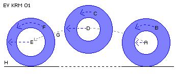 Within this phase of free flying, wheel will reduce its rotation (C)
around its own axis in benefit of correspondingly faster translation (D). By
this movement ahead of higher speed (E) wheel again hits onto road. Its mass
below, for short time, is forced to stand still on road, while all other mass
parts ´stumple´ over this point. Wheel thus again will show more rotation (F),
corresponding to meanwhile increased translation.
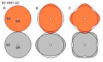 Main shaft (here system gear wheel) of any machine should turn steady.
If nevertheless, rotor gear wheel shall turn un-steady, design of gear like
marked at B would do. So non-concentric gear wheels are demanded, not exactly
elliptic (like simplified drawn here), but some kind of ´oval´ shape.
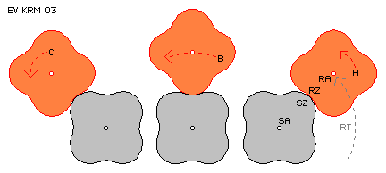 Supporting point at rotor right side is positioned near rotor axis, so
this ´small´ wheel (that very moment) has to turn fast, thus shows high rotation
(A) around its rotor axis. Rotor at middle of picture shows large radius versus
system gear wheel, so rotor there will show slower rotation. Correspondingly
faster its movement ahead (B) will be, thus rotor shows faster ´translation´ at
circled track around system axis.
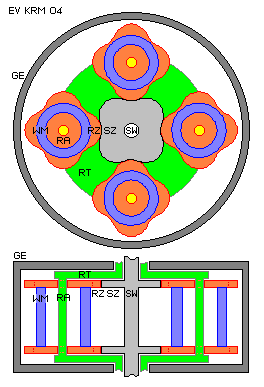 Withing
housing (GE, German Gehäuse) system shaft (SW, German Systemwelle) tournably is
beared. Fix connected with system shaft (SW) are both system gear wheels (SZ).
Each is in connection (by wandering supporting point above) with four rotor gear
wheels (RZ). Rotor gear wheels (RZ) are guided by its rotor axis (RA)
concentrically around system axis. This function is done by rotor arm (RT). This
rotor arm is free turnable around system shaft (SW) or its hollow shaft also
could reach outside of housing.